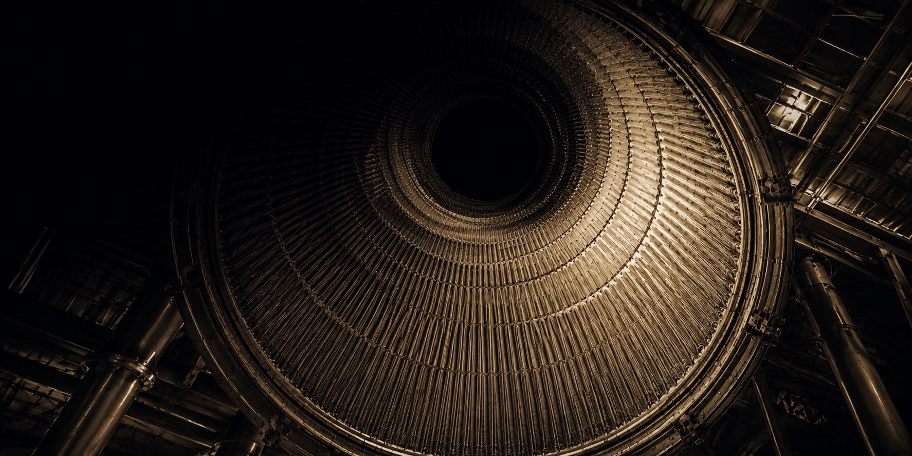
The Numbers
Begin with the specification, because the specification is genuinely difficult to believe.
Rocketdyne F-1 engine, principal characteristics
| Parameter | Value |
|---|---|
| Thrust at sea level | 6,770,000 newtons |
| Thrust in vacuum | 7,770,000 newtons |
| Propellants | RP-1 kerosene and liquid oxygen |
| Mixture ratio, oxidiser to fuel | 2.27 to 1 |
| Total propellant flow | 2,578 kilograms per second |
| Liquid oxygen flow | 1,789 kilograms per second |
| Kerosene flow | 788 kilograms per second |
| Chamber pressure | 70 bar |
| Combustion temperature | About 3,300 kelvin |
| Specific impulse, sea level | 263 seconds |
| Specific impulse, vacuum | 304 seconds |
| Nozzle exit diameter | 3.7 metres |
| Overall height | 5.6 metres |
| Dry mass | 8,400 kilograms |
| Turbopump output | 41,000 kilowatts |
| Turbopump speed | 5,550 revolutions per minute |
| Burn duration | 165 seconds |
| Engines per Saturn V first stage | Five |
Take the flow rate first, because it is the number that resists intuition. Two and a half tonnes per second. An F-1 emptied an Olympic swimming pool of propellant in about fifteen seconds. Five of them together consumed thirteen tonnes per second, and the first stage carried 2,160 tonnes of propellant to feed them for less than three minutes.
Take the turbopump next. Forty-one thousand kilowatts is 55,000 horsepower, which is roughly the output of a large naval destroyer's entire propulsion plant, produced by a machine that would fit in a domestic garage and that ran for 165 seconds before being thrown into the Atlantic.
And take the nozzle. Three point seven metres across at the exit -- wide enough to park a car in.
There is a persistent claim that the F-1 remains the most powerful rocket engine ever built. That needs qualifying. The Soviet RD-170, developed for the Energia launcher in the 1980s, produced 7,900,000 newtons at sea level, more than the F-1. But it did so through four separate combustion chambers fed by one turbopump. As a single-chamber engine, the F-1 has never been exceeded, and given that modern practice favours clustering many smaller engines for reliability and reusability, it is unlikely to be. Settled
How the Pump Was Driven
Before anything else can be understood about the F-1, the cycle has to be understood -- the arrangement by which the turbopump is powered.
The problem is circular. To burn propellant at high pressure you must pump it. To pump it you need power. The only energy source aboard is the propellant itself. So some of the propellant must be diverted to drive the pump, and every kilogram diverted is a kilogram not producing thrust efficiently.
There are three standard answers.
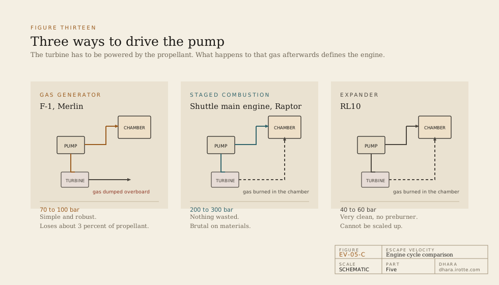
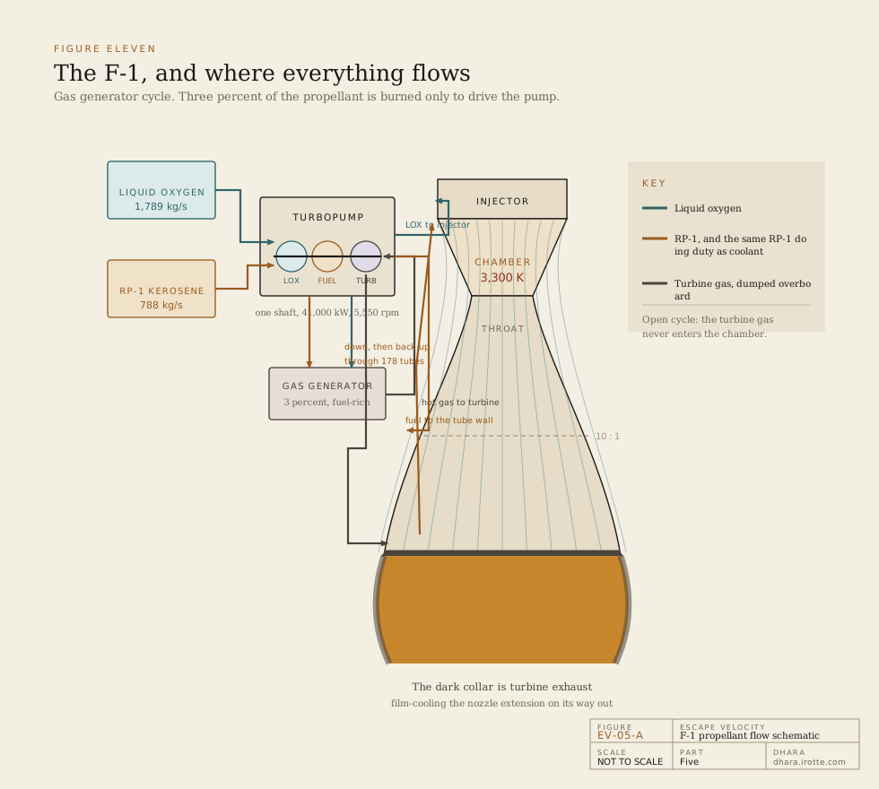
The gas generator cycle, which the F-1 used. A small fraction of the propellant -- about three percent -- is burned in a separate small combustion chamber called a gas generator, deliberately very fuel-rich so that the resulting gas is relatively cool. That gas drives the turbine and is then dumped overboard. It is called an open cycle because the turbine exhaust never enters the main chamber and contributes almost nothing to thrust.
The staged combustion cycle, used by the Space Shuttle Main Engine and by the Soviet RD-170. The turbine drive gas, after passing through the turbine, is routed into the main combustion chamber and burned properly. Nothing is wasted. The penalty is that the preburner and turbine now operate at pressures higher than the main chamber, which is brutally demanding on materials.
The expander cycle, used by the RL10. No combustion at all in the drive loop: the fuel is heated by the chamber walls it is cooling, expands into gas, drives the turbine, and is then burned in the main chamber. Elegant, efficient, and limited to small engines, because the heat available scales with chamber surface area while the power needed scales with volume.
The three principal engine cycles compared
| Cycle | Example | Turbine gas fate | Typical chamber pressure | Trade |
|---|---|---|---|---|
| Gas generator, open | F-1, Merlin | Dumped overboard | 70 to 100 bar | Simple and robust, loses about 3 percent of propellant |
| Staged combustion, closed | Space Shuttle Main Engine, RD-170, Raptor | Burned in main chamber | 200 to 300 bar | Highest efficiency, extreme material demands |
| Expander, closed | RL10 | Burned in main chamber | 40 to 60 bar | Very clean, cannot scale to large engines |
The F-1's designers chose the gas generator cycle because it was the only one anyone was confident could be scaled to that size in the time available. It cost roughly three percent of the propellant and perhaps fifteen seconds of specific impulse. It bought a machine that could be built.
The turbine exhaust had one further use, and it explains something visible in every photograph of a Saturn V launch. Rather than venting the gas directly overboard, it was routed into a manifold and injected as a cool curtain along the inside of the nozzle extension below the ten-to-one expansion point, protecting that section from the main flame. It emerged around the rim of the plume as a darker, sooty, fuel-rich collar. The dark ring visible around the base of each F-1's exhaust is turbine exhaust doing a second job on its way out.
The Pump
The F-1 turbopump is a single shaft with three machines on it: a two-stage turbine at one end, a kerosene impeller in the middle, and a liquid oxygen impeller at the far end.
That arrangement is, considered honestly, alarming. Kerosene and liquid oxygen are separated on a common rotating shaft by nothing but seals, and a seal failure that allows them to meet inside the pump housing produces an explosion in the middle of the machine that is feeding the engine.
The solution was an interpropellant seal assembly: not one seal but a stack, with a drain cavity between the fuel side and the oxidiser side that was purged with inert gas and vented overboard through a duct. Any leakage from either side entered the cavity and was expelled before it could reach the other. The vent duct was an item of extremely close inspection, because a blockage in it meant the two propellants were being held apart by nothing but hope.
Two further constraints shaped the pump.
The bearings could not be lubricated with oil. Oil freezes at liquid oxygen temperature, and oil in contact with liquid oxygen is a detonable mixture. So the bearings were cooled and lubricated by the propellants themselves -- kerosene on the fuel side, liquid oxygen on the oxidiser side, flowing continuously through the bearing races.
And the pump inlets had to be protected from cavitation. Liquid oxygen at 90 kelvin is close to boiling at any pressure it is likely to encounter, and a local pressure drop at the leading edge of an impeller blade will flash it to vapour. The vapour bubbles then collapse against the metal with enormous local force and erode the impeller from the inside out. The answer was an inducer -- a low-pressure axial screw mounted ahead of the main impeller, whose only job is to raise the inlet pressure just enough that the main impeller never sees the liquid near its boiling point.
Every large pump-fed rocket engine built since fights these same three problems in the same terms.
A Wall Made of Pipes
The thrust chamber is where the F-1 stops being an impressive machine and becomes a beautiful one.
The problem, stated plainly: the gas inside is at about 3,300 kelvin. Inconel melts at about 1,660 kelvin. Steel fails at 1,700. Tungsten, the highest-melting metal there is, melts at 3,695 and is unworkable for this purpose. The chamber must contain, for 165 continuous seconds, a fire hotter than the melting point of anything it can be made of.
The F-1's answer was to make the wall out of the coolant pipes themselves.
The chamber and the upper nozzle were constructed from 178 primary tubes of Inconel X-750, a nickel-chromium superalloy, each drawn and bent to a precise contour that followed the chamber profile -- narrowing at the throat, flaring into the bell. Because the circumference grows toward the nozzle exit, the tubes bifurcate partway down, each splitting into two, so that the wall remains continuous as the diameter increases. The tubes were then furnace-brazed to one another along their entire length into a single gas-tight shell, wrapped externally with reinforcing bands and a structural jacket.
There was no separate liner. The wall was pipes, and nothing else.
Kerosene entered a manifold partway down the nozzle, flowed down through half the tubes to the exit end, turned, and flowed up through the other half back to the manifold, and from there to the injector to be burned. Every square centimetre of the chamber's inner surface therefore had cold kerosene moving on the far side of a wall about half a millimetre thick.
Temperature across the F-1 chamber wall at the throat
| Location | Approximate temperature |
|---|---|
| Combustion gas core | 3,300 kelvin |
| Gas-side tube surface | 800 to 1,000 kelvin |
| Coolant-side tube surface | 500 kelvin |
| Kerosene in the tube | 300 to 400 kelvin |
| Distance across which this occurs | About 0.5 millimetres |
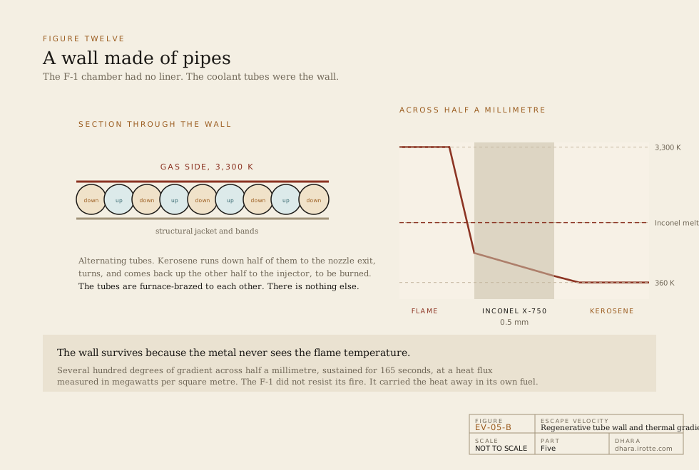
Read the last two rows together. A temperature difference of several hundred degrees, across half a millimetre of metal, sustained for nearly three minutes, at a heat flux measured in megawatts per square metre -- among the highest sustained heat transfer rates achieved in any engineering discipline.
Below the ten-to-one expansion point the tubes stopped and a separate nozzle extension took over, cooled not regeneratively but by the film of turbine exhaust described above. It was a cheaper solution for the region where heat loads had fallen, and it saved considerable mass.
The F-1 did not resist its own flame. It carried the flame's heat away, continuously, in the fluid it was about to burn.
The Screaming
Now the crisis.
A combustion chamber is an enclosed volume of gas, and every enclosed volume of gas has acoustic resonances -- modes at which a pressure wave can travel around or across the volume and reinforce itself. In a small chamber these modes sit at frequencies and amplitudes that do not matter. In a chamber 1.0 metre across, they matter enormously.
The mechanism is a feedback loop. Suppose a slight pressure wave crosses the chamber. Where the pressure is momentarily higher, propellant droplets break up and vaporise faster, so combustion in that region is briefly more intense, which releases more heat, which raises the pressure further, which strengthens the wave. The wave reflects off the chamber wall and comes back. If the timing of the combustion response happens to match the acoustic period, the oscillation grows.
In the F-1 the dangerous modes were tangential -- pressure waves spinning around the circumference of the chamber -- at frequencies in the region of 2,000 to 3,000 cycles per second. Pressure swings reached and exceeded the entire steady chamber pressure, meaning the pressure at a given point was oscillating between roughly zero and twice nominal, thousands of times a second.
The consequence was not merely vibration. The oscillating flow destroyed the protective boundary layer against the wall, so the full flame temperature reached the metal directly. The engine burned through from the inside in a fraction of a second.
Two distinct instability modes encountered in F-1 development
| Mode | Frequency | Mechanism | Effect |
|---|---|---|---|
| Chugging, low frequency | Tens of cycles per second | Coupling between the combustion chamber and the propellant feed system | Rough running, structural loads, survivable |
| Screeching, high frequency | 2,000 to 3,000 cycles per second | Coupling between combustion and the acoustic modes of the chamber volume | Destruction of the chamber within a tenth of a second |
Nobody could predict it. That is the essential point, and it remains substantially true today. There was no theory that could take a proposed injector design and say whether the resulting engine would be stable. The physics involves the coupled behaviour of atomisation, droplet vaporisation, turbulent mixing, chemical kinetics and acoustics, over a range of length scales spanning six orders of magnitude, in a medium nobody could instrument directly.
The only available method was to build it and fire it and see.
Bombs
In 1962, NASA formed an ad hoc committee on combustion instability and Rocketdyne stood up a dedicated effort. The programme was reorganised around a single principle that changed everything.
They stopped trying to build an engine that would not become unstable. They started trying to build an engine that could recover from instability.
The distinction is profound. An engine that has never gone unstable on a test stand may simply not have been provoked. An engine that has been deliberately and violently disturbed, and returned to smooth running, has demonstrated something you can actually rely on.
So they provoked them. Small explosive charges were mounted in the chamber wall of a running engine and detonated during the firing, producing an instantaneous pressure disturbance far larger than anything expected in flight. Instrumentation recorded the chamber pressure oscillation that followed. The criterion adopted was that the engine must damp the disturbance and return to stable operation within 400 milliseconds. The best of the final configurations recovered in well under a hundred.
It took on the order of two thousand full-scale tests over roughly four years, at Santa Susana and at Edwards Air Force Base, consuming propellant and hardware on a scale that would today be difficult to justify to anyone.
The fix, when it came, was in the injector.
The original injector was a flat plate drilled with thousands of orifices, arranged so that fuel and oxidiser streams impinged on one another to atomise and mix. The redesigned injector kept that principle but added baffles: copper blades standing proud of the injector face, projecting into the chamber, dividing the volume immediately beneath the injector into thirteen separate compartments -- a central hub with radial spokes.
The baffles do not prevent combustion oscillation. They break up the tangential acoustic modes, so that a pressure wave attempting to spin around the circumference cannot complete the circuit, and the volume available to any single mode is small enough that its frequency moves away from the combustion response. The baffles themselves were fuel-cooled, hollow, and part of the injector's flow circuit, because a solid copper blade in that environment would have melted.
Alongside the baffles, the orifice pattern was altered repeatedly -- impingement angles, orifice diameters, the arrangement of fuel and oxidiser holes relative to one another, and the deliberate reduction of injection velocity in the outer ring to create a slightly fuel-rich, cooler boundary layer along the wall.
The combustion instability campaign
| Measure | Figure |
|---|---|
| Duration of the campaign | Roughly 1959 to 1965 |
| Full-scale engine tests | About 2,000 |
| Injector configurations evaluated | Over 40 |
| Deliberate bomb-induced disturbances | Hundreds |
| Recovery criterion adopted | Stable within 400 milliseconds |
| Recovery achieved by final design | Under 100 milliseconds |
| Combustion instability failures in flight | None, across 65 engines flown |
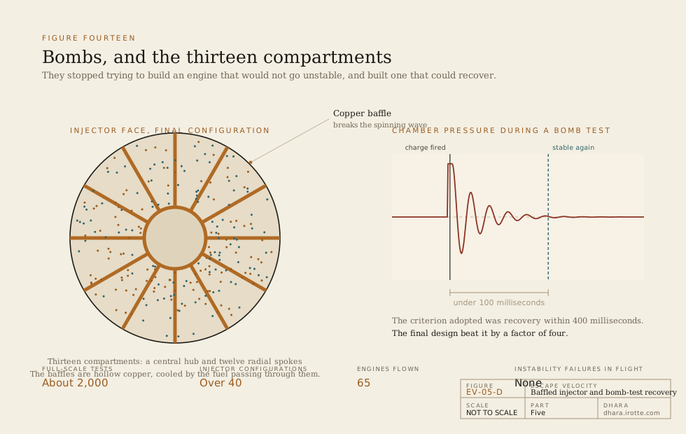
That final row is the one that matters. Sixty-five F-1 engines flew, on thirteen Saturn V launches, and not one of them suffered a combustion instability failure.
The solution was not understood in the sense that a theory was produced from which it followed. It was found. Engineers today can model these phenomena far better than in 1962, and combustion instability is still an empirical discipline in which new engines are bomb-tested because nobody entirely trusts the models. Still true
Starting It
Kerosene and liquid oxygen are not hypergolic. Put them together and nothing happens. Something must light them, and lighting 2,578 kilograms per second of propellant is not a job for a spark plug.
The F-1 was started by a cartridge of triethylaluminium and triethylborane -- a mixture that ignites spontaneously and violently on contact with oxygen, and burns in air on contact with nothing at all. The cartridge was sealed with burst diaphragms at both ends. When fuel pressure rose sufficiently during the start sequence, the diaphragms ruptured, the mixture was pushed into the injector ahead of the main kerosene flow, and it met the incoming oxygen and lit. The main flow arrived into an already-established flame.
The same trick, with the same chemicals, starts the Merlin engines flying today.
The start sequence itself was a choreography lasting several seconds, in which the gas generator was lit first to spin up the turbopump, pump discharge pressure rose, the main oxidiser valve opened, then the igniter fired, then the main fuel valve opened in a controlled ramp. Open the valves in the wrong order or the wrong interval and propellant accumulates in the chamber before ignition, producing a hard start -- which is a polite term for the chamber becoming a bomb.
On the Saturn V, the five engines were not started simultaneously. The centre engine lit first, then the two opposing outboard pairs at intervals of about 300 milliseconds, so that the structure was loaded progressively rather than shocked. From the first ignition to full thrust on all five took about eight seconds -- and only then, with all five verified, did the hold-down arms release.
The centre engine was fixed. The four outboard engines were gimbal-mounted and could pivot up to about five degrees for steering. And at 135 seconds into the flight, the centre engine was shut down deliberately, because as the vehicle lightened the acceleration was approaching four times gravity and would have exceeded what the structure and the crew were rated for.
What Became of Them
Sixty-five F-1s flew. Ninety-eight or so were built. The last flew in May 1973, lifting Skylab on the final Saturn V.
The production line was shut down, and the tooling was dispersed or destroyed. This is often described as a scandal, and it deserves a more careful judgement: the engine was designed for an industrial base of the 1960s, with hand-brazed tube assemblies and manufacturing practices that no longer exist. Rebuilding it would mean redesigning it, which is why the F-1B studies of the 2010s -- proposing a simplified, channel-wall version for a Space Launch System booster -- were never a matter of simply reopening a factory. Contested
In 2013 an expedition funded by Jeff Bezos located F-1 engine components on the Atlantic seabed several hundred kilometres off the Florida coast, in water about 4,300 metres deep, and recovered substantial pieces, including thrust chambers and injectors, from engines that had flown Apollo missions. Serial numbers were later identified. Several are now on public display, salt-corroded and torn, which is the correct condition for them to be seen in.
What Comes Next
The F-1 lifted the vehicle for 165 seconds and reached an altitude of about 68 kilometres and a speed of 2,750 metres per second. Then it fell away, and the job passed to an engine built on a completely different principle, burning a propellant that is both the best and the worst substance ever put in a rocket.
The next part is about liquid hydrogen.
It covers why hydrogen gives forty percent more exhaust velocity than kerosene and why that forty percent, sitting inside a logarithm, was the difference between a lunar mission that closed and one that did not. It covers what it means to handle a liquid that boils at 20 kelvin, has one fourteenth the density of water, leaks through joints that hold every other substance, and makes steel brittle simply by being in contact with it.
It covers the J-2, and the augmented spark igniter that let it be shut down in orbit and restarted an hour and a half later in vacuum -- an ability nobody had needed before and without which no one would have gone to the Moon.
And it covers the S-II's common bulkhead: a single shared dome between the hydrogen tank and the oxygen tank, with a temperature difference of 70 kelvin across a honeycomb core a few centimetres thick, which saved three and a half tonnes and very nearly could not be built.
0 responses